![]()
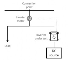
Any execution of these test procedures will require an electrical test setup as shown in the figures below:
| Component | Additional requirement |
Inverter | Configured to receive commands from a communications software client (native, gateway or cloud) | |
Inverter meter | Measures or enables calculation of net export | |
DC source | PV panels or DC supply of at least 2kW DC during test execution. (Inverters less than 2kW in capacity will be handled individually). | |
Load | At least 500W of switchable load |
Figure 7: Test Setup for Single Inverter
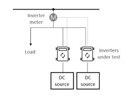
Multiple inverter support tests will require an electrical test setup as shown in the figure below:
| Component | Additional requirement |
Inverter (minimum 2) | Configured to receive commands from a communications software client (native, gateway or cloud). Both inverters to be below the same common metering point. | |
Inverter meter | Measures or enables calculation of net export | |
DC source | PV panels or DC supply of at least 2kW DC during test execution. | |
Load | At least 500W of switchable load |
Figure 8: Test Setup for Multiple Inverters
The party undertaking the test is responsible for ensuring a test setup is available during test execution.
![]()
The below functions from CSIP-AUS and IEEE 2030.5:2018 are required to be supported in addition to any other common functionality required to support the following:
• DeviceCapability
• Time
• EndDevice
• FunctionSetAssignments
• DER
- DERList
- DERSettings
- DERStatus
- DERCapability
- DERProgram
- DERControlList
- DefaultDERControl
- Randomisation
- Scheduling
• Response
- DERControlResponse
• Metering Mirror
- MirrorUsagePoint
- MirrorMeterReadingList
- MirrorMeterReading
- MirrorReadingSet
- Reading
• Subscription/Notification
• ConnectionPoint Extension
![]()
Upon initial discovery, the Utility Server will configure the following poll and post rates for resources as per the table below.
Please note these values are for testing purposes and do not reflect steady state operation requirements for our Minimum Demand Production systems.
Table 7: Default Poll and Post Rates
Resource | Type | Value (secs) |
Device Capability | Poll | 60 |
EndDeviceList | Poll | 60 |
FunctionSetAssignmentList | Poll | 60 |
DERProgramList | Poll | 60 |
DERList • DERStatus • DERSettings • DERCapability | Poll | 60 |
MirrorUsagePoint | Post | 60 |